Repairing a Broken Multimeter
In December 2017 my multimeter broke.
It no longer measured resistance correctly.
For low resistances, the numbers looked alright, but with bigger resistances, the value didn’t go higher than about 40kΩ.
I only had one multimeter, so I didn’t have anything to compare against, so how did I determine that it’s broken for sure?
It seemed to measure 1kΩ accurately, so I used Ohm’s Law and connected 10 of the 1kΩ resistors in series.
It read about 7kΩ. Uh, oh.
I ordered a new one, same model. I complained to my friends on Facebook and got some pity likes. I didn’t know much about electronics, so I accepted that the old one is broken and only trusted the new one. Until it broke as well. In a similar way.
How did I break it? To be honest, I don’t know. I assume it was a user error. If I had to guess I either tried to measure the resistance on a powered circuit or tried to measure current with the red lead still in the Voltage/Resistance socket.
Last year I asked Santa for a different multimeter as I was tired of buying them myself. After learning some more electronics theory I decided to take a look and try to fix it.
The patient
I had two patients with similar, but not the same symptoms.
One of them topped up resistance measurements at 40kΩ and another at 5kΩ.
They are the same Proster VC97 Digital Multimeter.
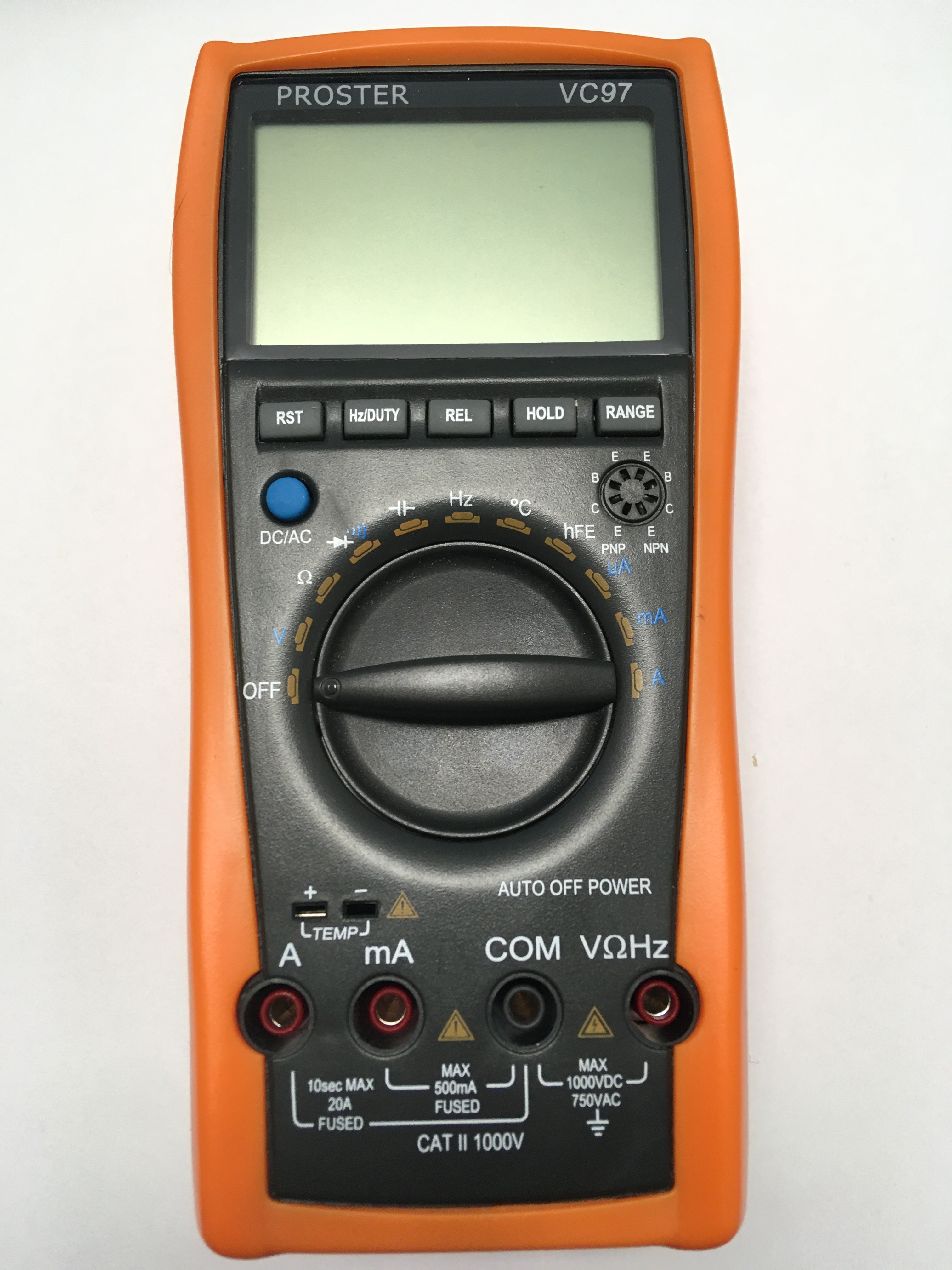
Proster VC97 Multimeter
Sanity checks
I wanted to try some easy things before diving deep and trying to understand the root cause.
Here’s what I tried:
- replaced the batteries with fresh ones
- checked the fuses with a continuity check
- inspected the board visually, for signs of fried components or shorts
- cleaned the board with isopropyl alcohol in case some residue was creating shorts
- checked the resistors if they match the values on the package
None of it helped.
Deep dive
It was time to understand how the device is supposed to work and figure out why it doesn’t.
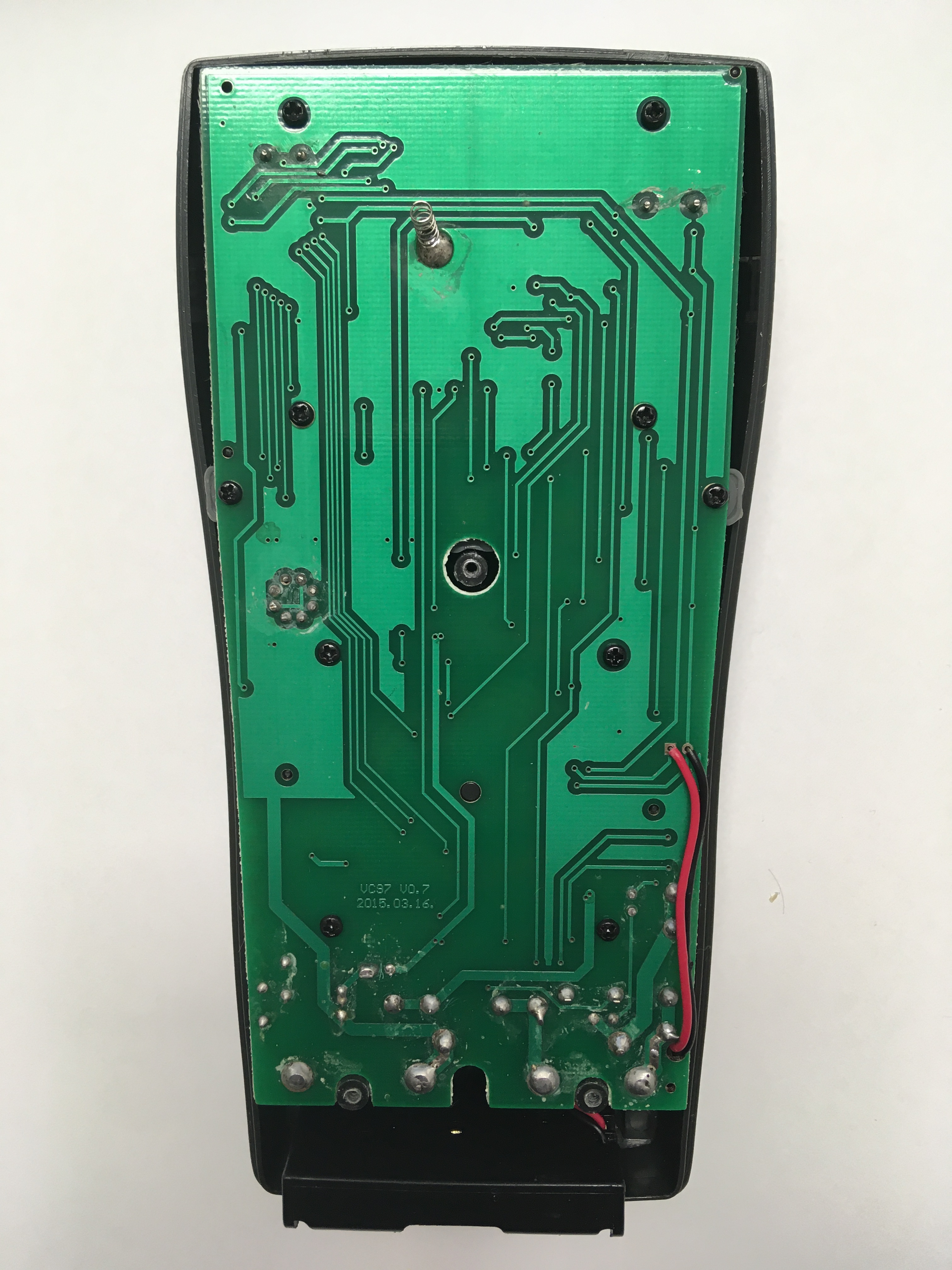
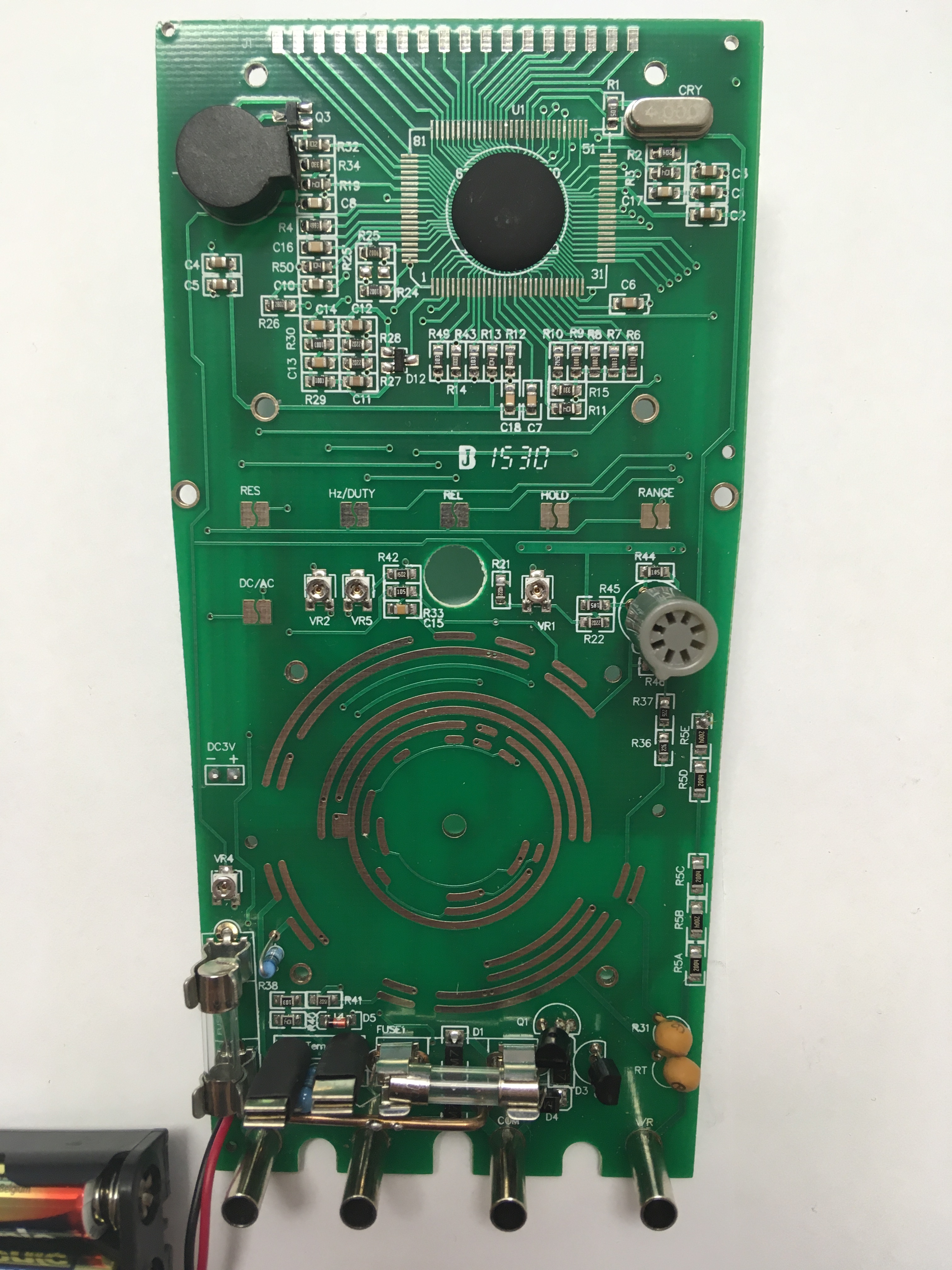
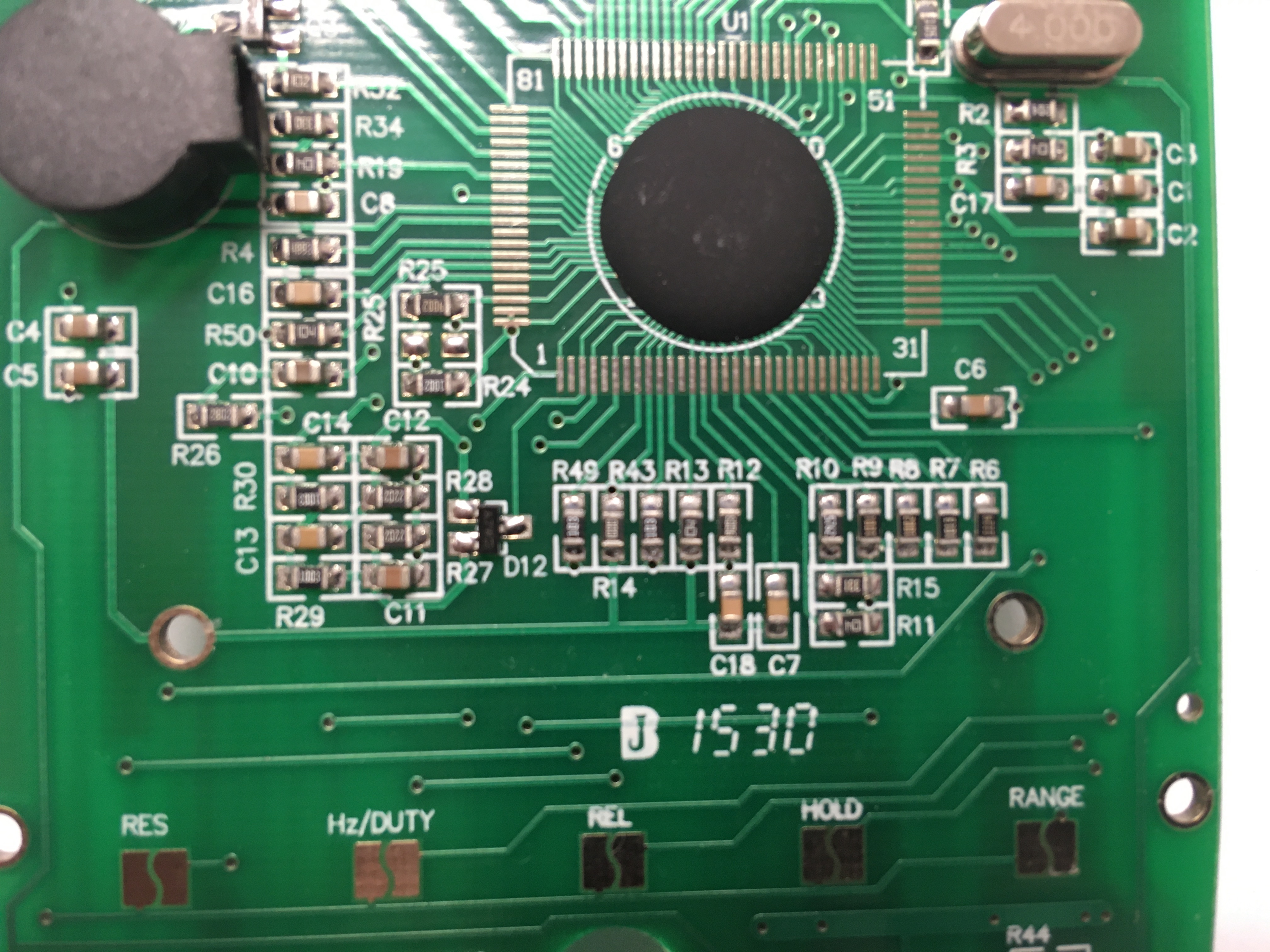
Back board
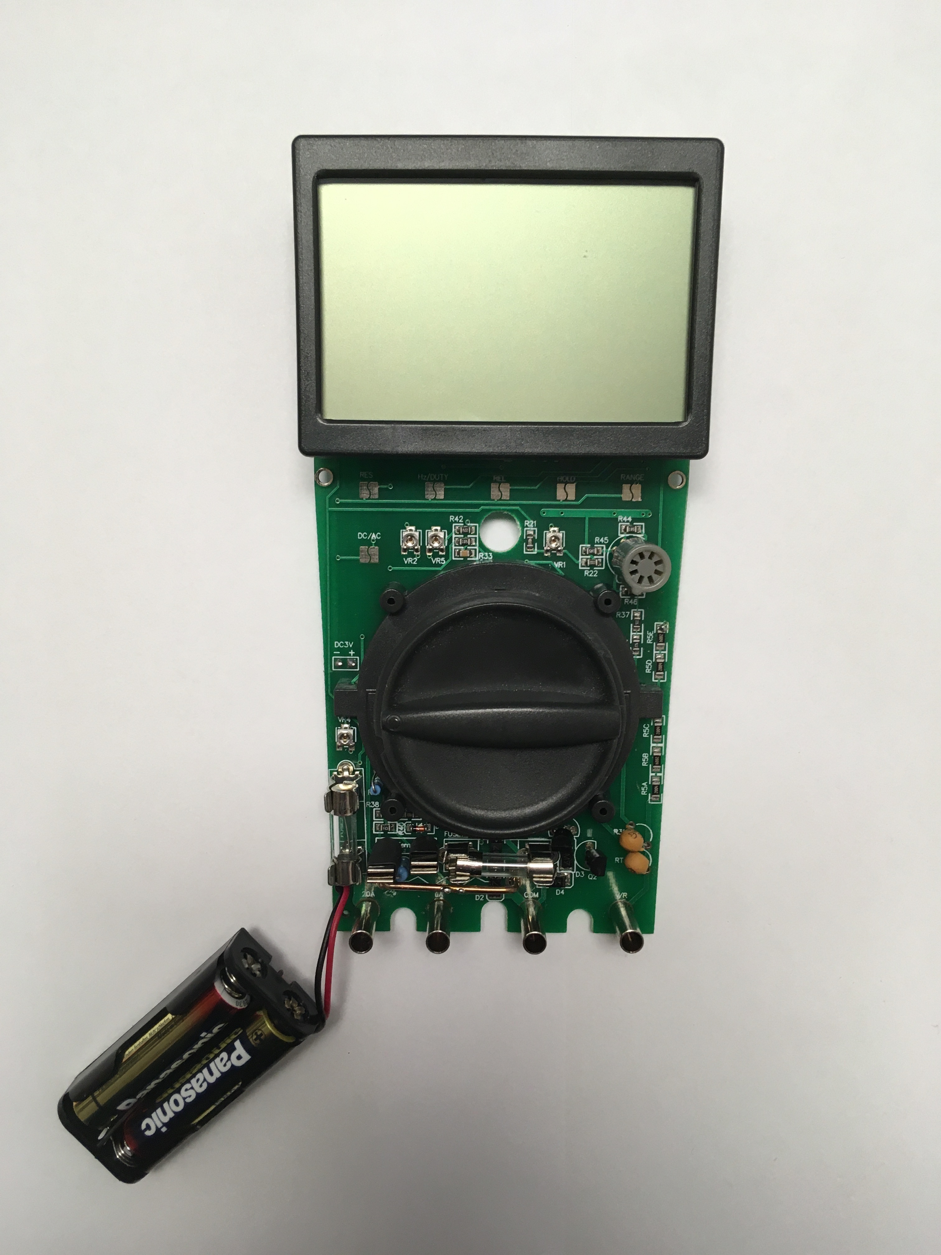
Front board with the dial and LCD
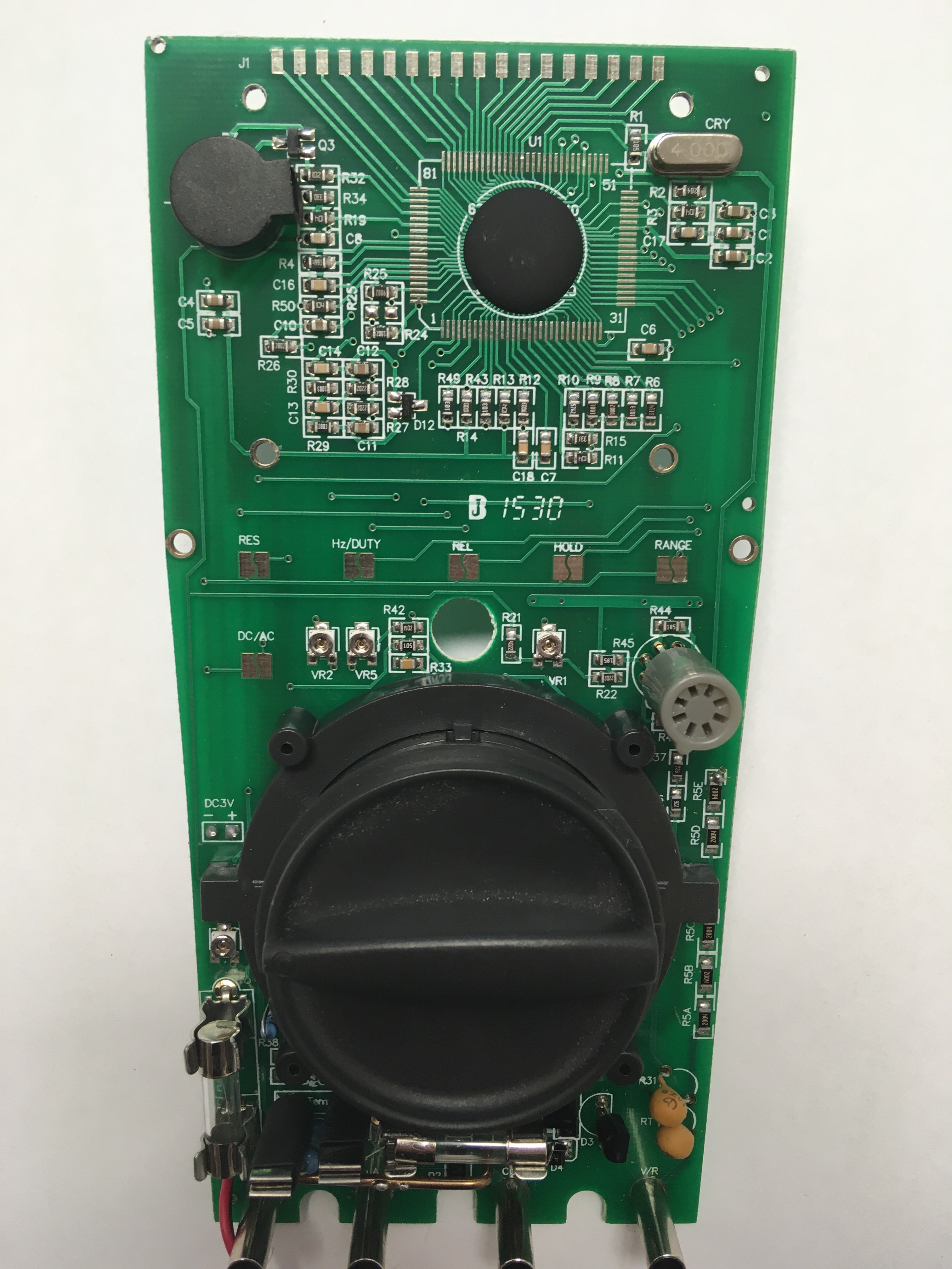
Front board with the dial
Front board
I looked at the board and recognized most of the elements: smd resistors, smd capacitors, through-hole resistors, fuses, smd potentiometers.
There were some I didn’t immediately recognize.
It took me some googling to figure out that MZ5 is a PTC (Positive Temperature Coefficient) thermistor.
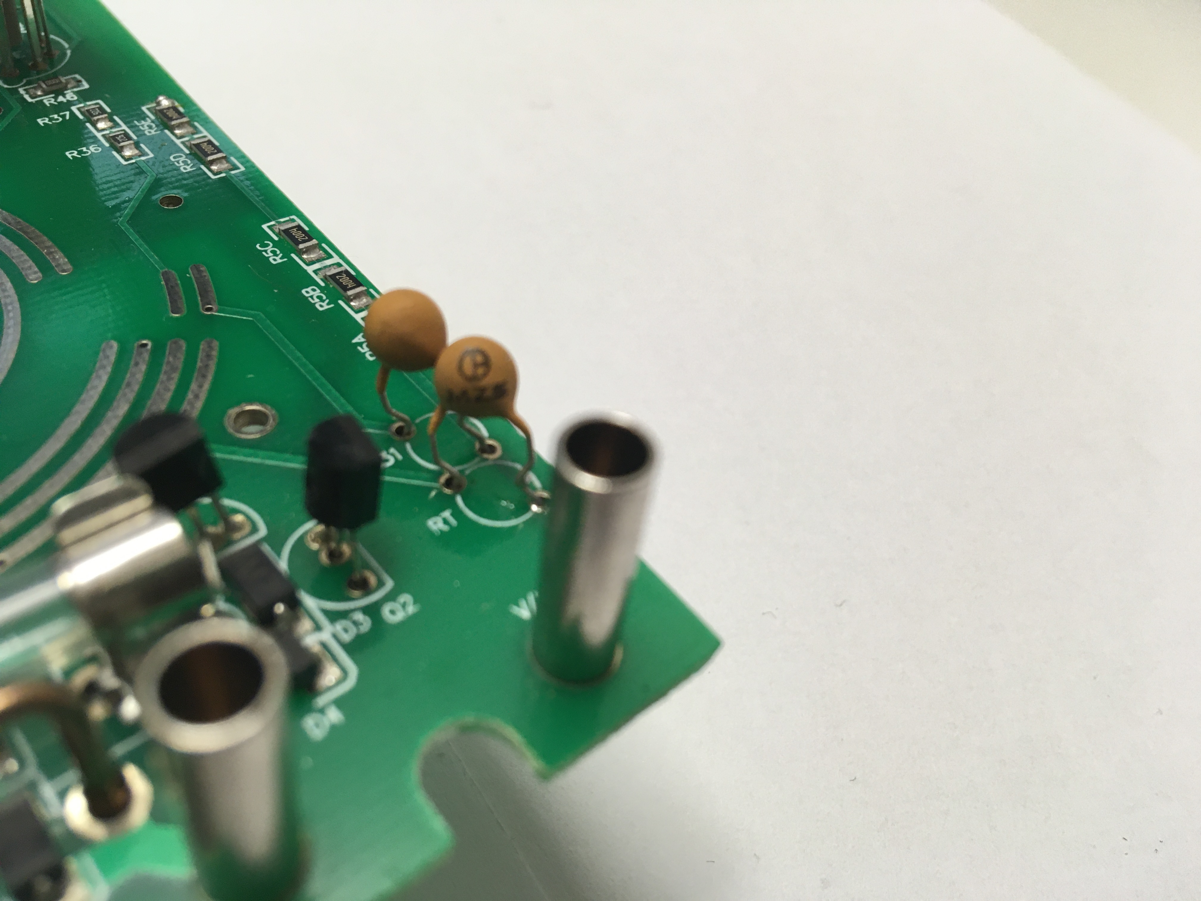
MZ5
What didn’t look good was that at the top of the board there was 100-pin IC hidden under a thick layer of opaque epoxy. The board had 2 layers of copper and multiple vias, so it was feasible, but a bit tedious to try to trace the connections.
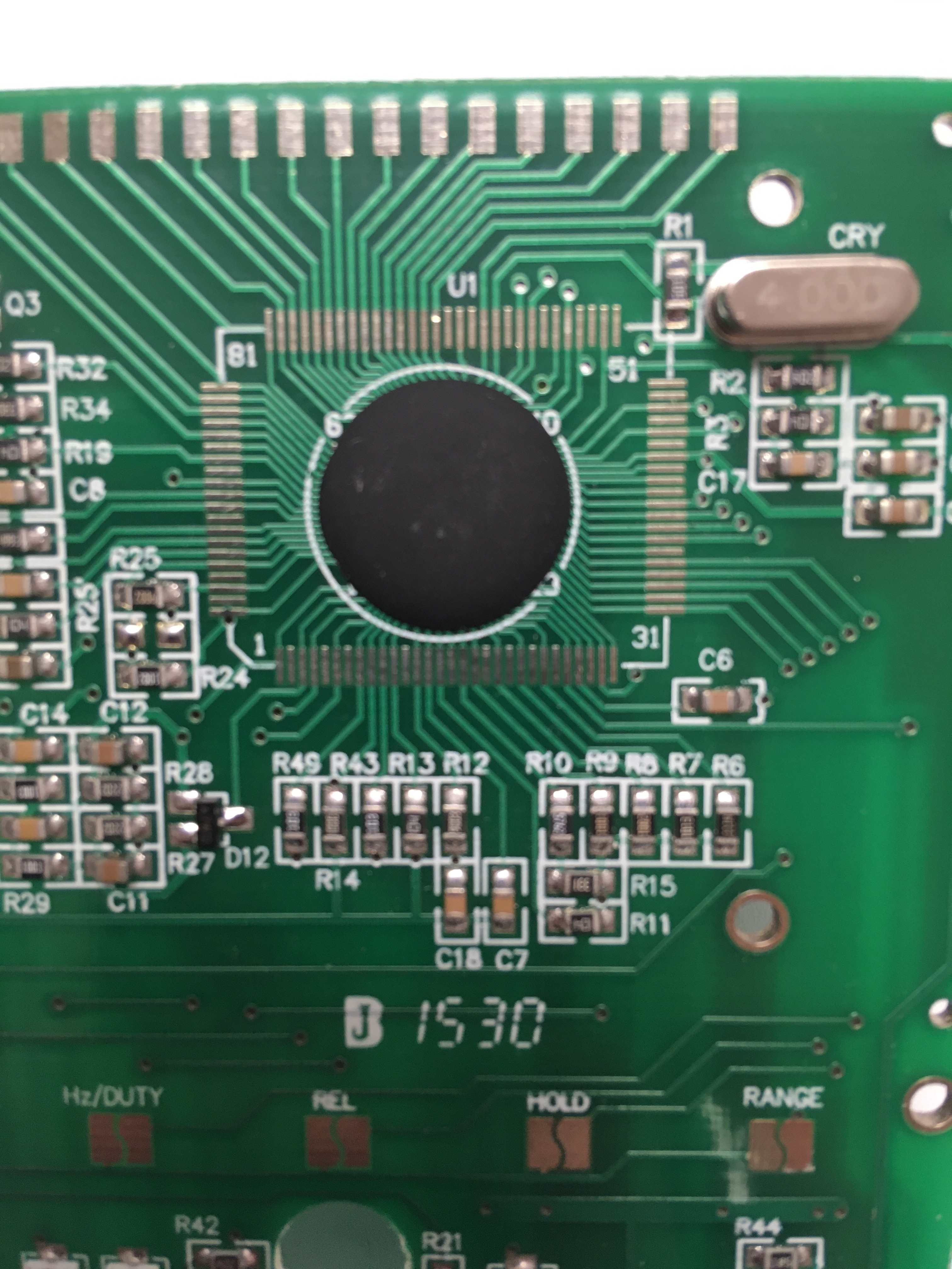
Mysterious IC
After some googling, I found a schematic for a VC97.
VC97 Schematic
I’m aware that there are multiple VC97 multimeters:
- Victor Digital Multimeter VC97
- AideTek VC97+ Digital Auto Range Multimeter
- Sinometer VC97 Auto Ranging True RMS Digital Multimeter
- Proster Digital Multimeter - mine
- NKTECH VICI VC97 LCD Digital Multimeter
I figured out that the schematic isn’t exactly for my model, as mine has 2 MZ5 PTC thermistors and is powered from 3V instead of 9V, but it looked close enough.
I had a 100-pin IC, a similar set of measurements, 4MHz clock, the same number of pins for the LCD and a lot of the pins agreed with connected resistors.
Based on the file name of the schematic I assume it’s for the Victor Digital Multimeter VC97 model.
I tried to figure out how it works on my own and a lot of it made sense, but I needed to know what the IC does.
The IC on the schematic is FS9711.LP1.
I googled for the IC datasheet, but I didn’t get an exact match. There’s a few IC’s matching the prefix.
My multimeter has 4,000 counts, so that narrows it down to 4 of them on the list.
It turns out that the -PCE suffix demarks a “Pb free package”, so that’s only 2 ICs: FS9721-LP1 and FS9721-LP3.
I started reading the FS9721-LP3 datasheet.
I understood that MEA1, MEA2, MEA3, MEA4 pins select the function.
I familiarised myself with all the pin functions and started marking out pins related to resistance measurements.
Section 10 describes how the function is selected and what the bit patterns are.
I wanted to confirm that I have at least a compatible IC, so I set my multimeter to Ohm meter and read out the pin values with another multimeter using a continuity check.
0011 is what I read. 1101 is what the IC wanted for resistance measurement.
Not my chip then.
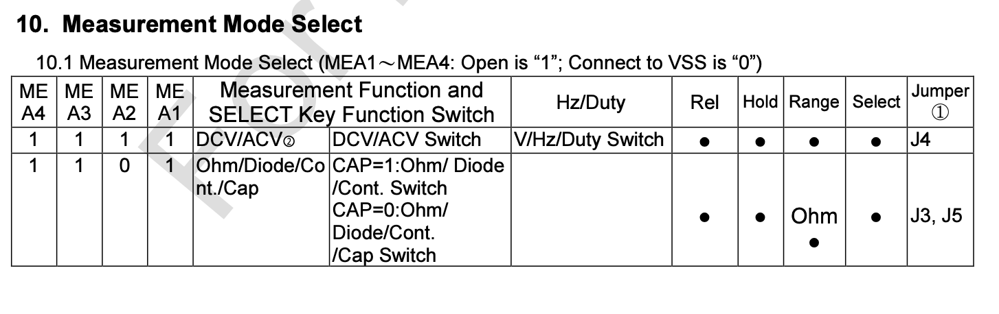
FS9721-LP3 measurement modes
Okay, next I try FS9721-LP1.
A quick look at the table in Section 10 confirmed that 0011 is resistance mode.
I checked the other modes and became more confident that I have the right chip.
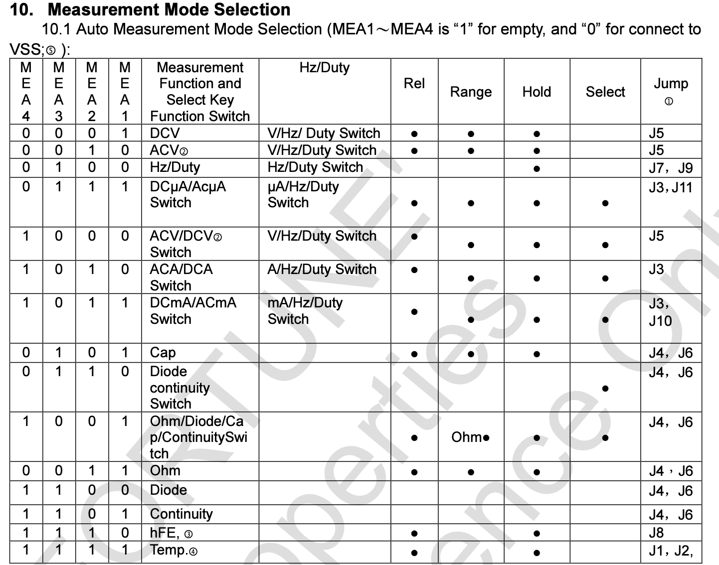
FS9721-LP1 measurement modes
In Section 14.1 there’s a Common Use Circuit Diagram, basically an example multimeter built with this chip.
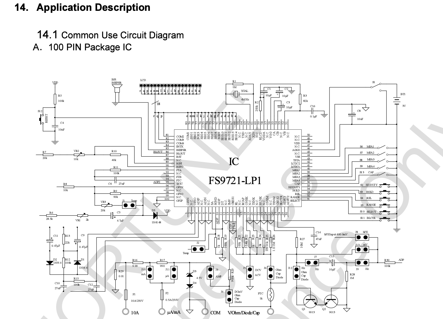
FS9721-LP1 Common Use Circuit
It’s different from the schematic that I found for VC97, but the reference resistances match and it’s more readable than the previous schematic.
It’s also easier to separate parts of the circuit for different measurements.
Sections 14.4 onwards focus on parts of the circuit and their purpose.
The power circuit has a diagram for voltage levels, so I confirmed that my multimeter matches them.
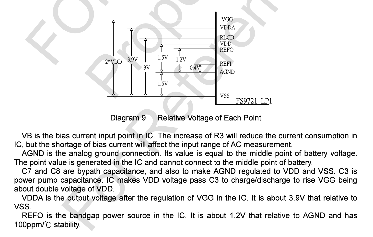
FS9721-LP1 Voltage Levels
There is a slight deviation in the REFI-AGND voltage, mine had 4.4V.
It turns out it’s adjustable with the VR1 potentiometer on my board, but I couldn’t get it below 4.2V.
Section 14.14 Resistance Measurement presents only parts relevant to the resistance measurement.
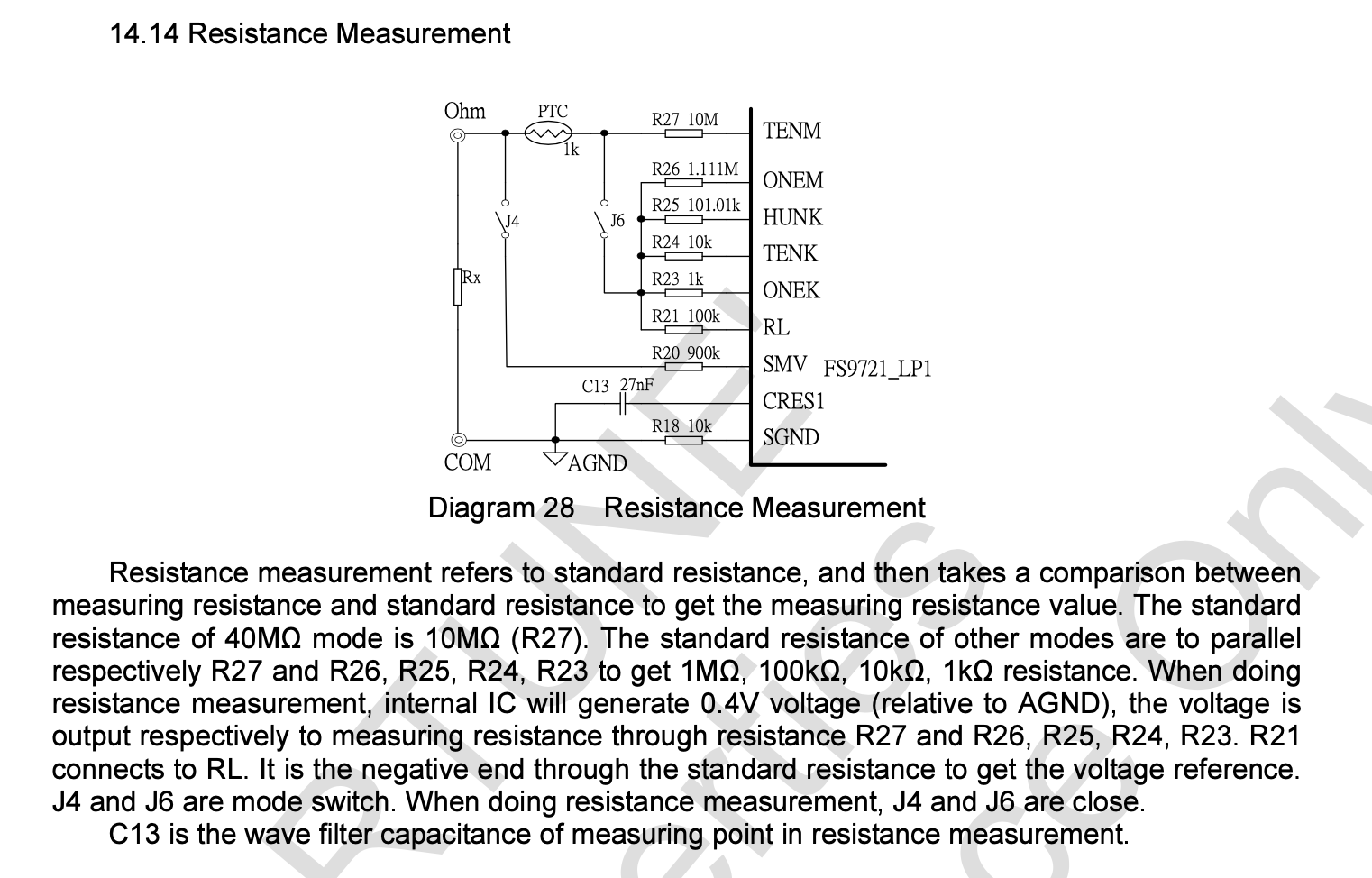
FS9721-LP1 Section 14.14 Resistance Measurement
It’s a simple circuit with Rx being the resistance being measured.
One easy thing to tell is that the COM and Ohm terminals don’t connect before they go into the IC, so the resistance between them should be high if not infinite.
I set my unpowered multimeter to Ohm mode and measured the resistance between COM and Ohm with a working multimeter.
38kΩ. Huh. That’s pretty low, it seems that I have a short.
A little digression on how the multimeter dial works.
On the board, there’s a set of concentric circles with partly exposed copper.
On the bottom of the dial, there are small V-shaped metallic springs that connect the adjacent traces of copper when in the right position.
I wanted to isolate the part of the circuit that causes the short, so I removed the springs until the short was gone.
The last spring to remove pointed me to the two copper traces that when connected cause a short.
This allowed me to focus on smaller parts of the circuit until I narrowed it down to a capacitor that measured 38kΩ across it - C18.
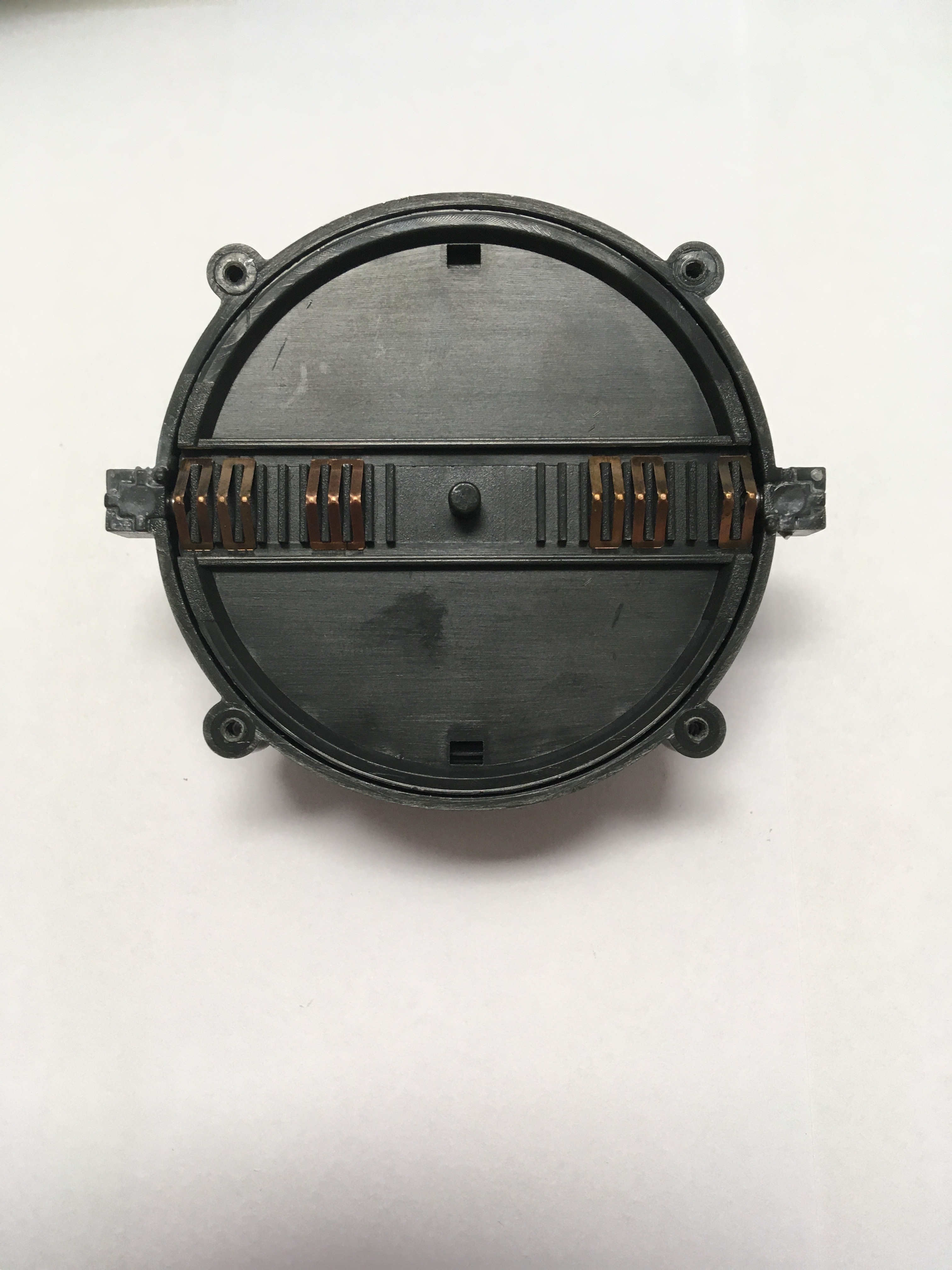
Back of the dial
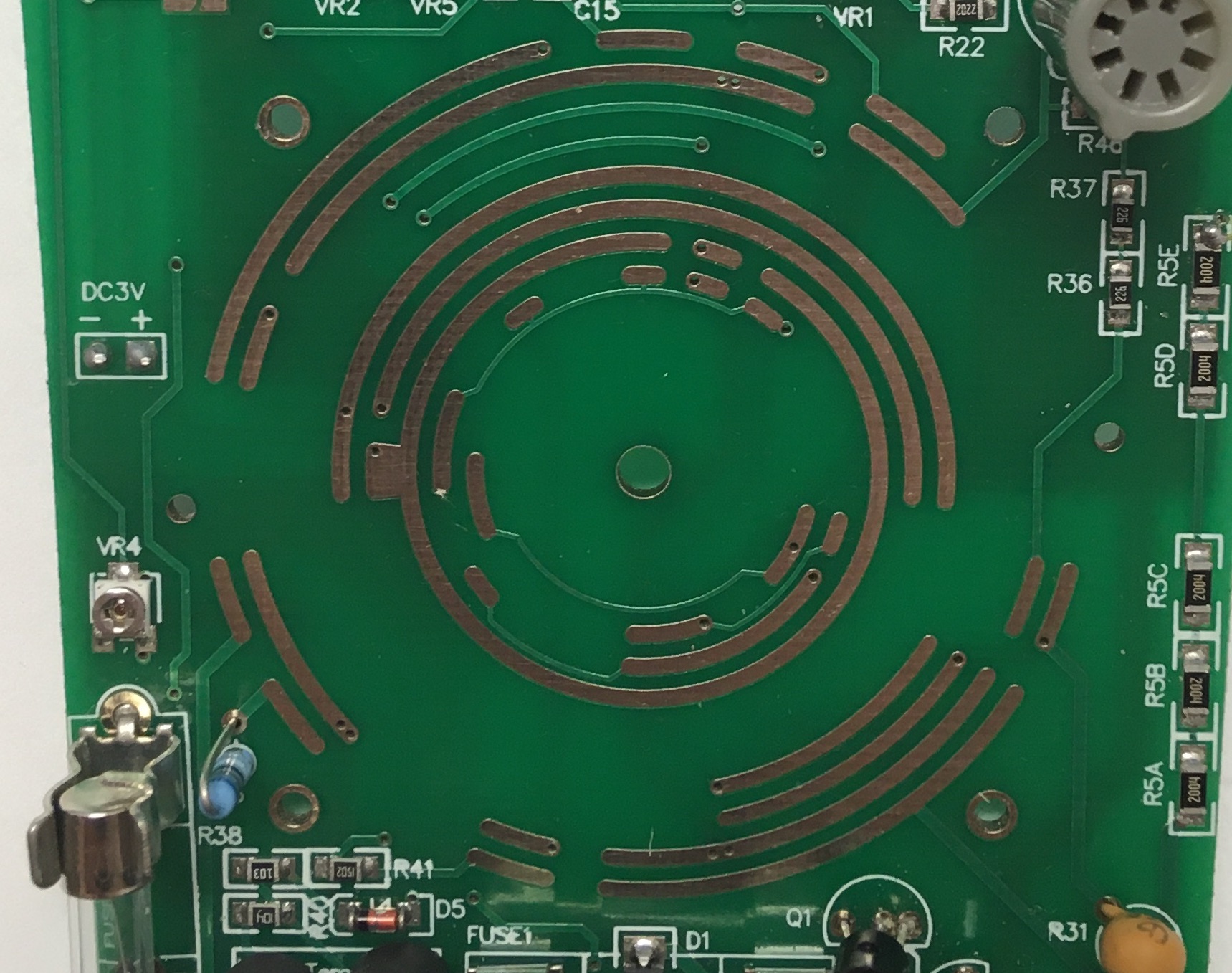
Exposed copper
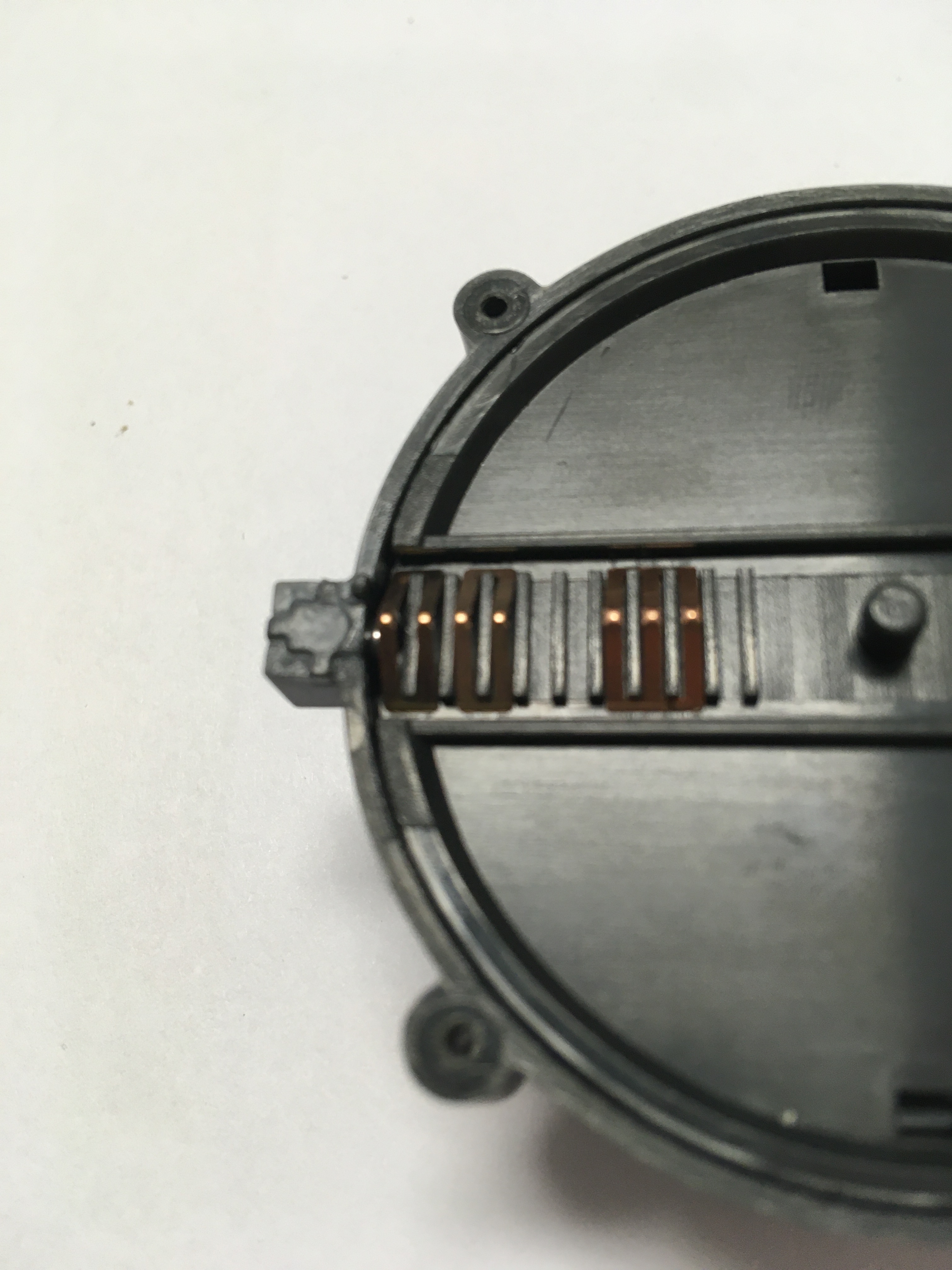
The V-shaped springs
Now notice that at the beginning of the troubleshooting I didn’t check the capacitors.
I didn’t know how I was supposed to check them.
As I understood measuring capacitance in-circuit doesn’t work and the capacitors are unmarked, so even if I determined their capacitance I had nothing to compare against.
Maybe one of the schematics, but none of them were for my exact multimeter, so I didn’t want to do that.
After I finally found the “38kΩ capacitor”, it didn’t seem right to me, but I wasn’t sure what I should expect, so I googled.
It turns out when you try to measure the resistance across a capacitor it’s supposed to start at some resistance and the resistance should “grow” as the capacitor gets charged.
Other capacitors in the circuit did that and C18 didn’t. I concluded it was faulty.
I checked C18 on the other broken multimeter, the same thing, only different “resistance” - 5kΩ.
C18 - the culprit
I have an assortment of smd capacitors, so I would happily replace it, but what capacitance is it supposed to be? None of the schematics I looked at even use a capacitor there and I don’t have a same-model working multimeter, so I didn’t know what to replace it with. So I took a leap of faith and desoldered it.
I reassembled the multimeter and it worked! It measured correct resistances again! But what did I break?
[UPDATE: 02.06.2022]
The mystery of C18 is solved in Repairing a Broken Multimeter Part 2.